
Dr.-Ing. Georg Wazau Mess- + Prüfsysteme GmbH
A specialist in the development and production of sophisticated precision measurement and testing systems with over 90 years of experience, serving industries like material testing, tribology, and fire safety.
All Products(53)
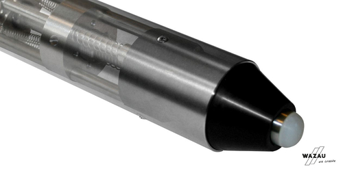
Impact hammer HFP
A bolt hits construction elements/construction element covers with a defined energy measures limits and tests resistance against discrete impact energy
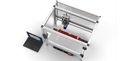
Solderability testing device type LPL
The device is used to determine the solderability of electrical components according to DIN EN 60068-2-20. It is equipped with 2 solder baths. . It has a lifting device that allows a defined immersion and withdrawal of specimens at immersion speeds from 0 to 45 mm/s. The lifting device has a max. travel of approximately 25 mm. The immersion time is controlled by the device software. The immersion speed and the dwell time in the solder bath are set and controlled by the software. The temperature in each of the two solder baths can be adjusted via a PID- temperature controller in the range from room temperature to 450 °C. The device is provided with an enclosure, the door of which is equipped with a safety hinge switch.
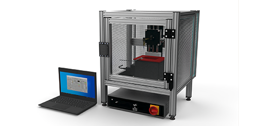
Solderability testing device type LPK
The device tests the solderability of metals under DIN EN 60068-2-20. The device has a lifting unit which allows a defined submerging and emerging of specimen with submerging speeds from 0,5 to 1001 mm/s. The lifting unit has a maximal lifting height of 25 mm. The device is works with a quartz controlled submerging duration of 0 to 10 s. The solder bath is of type ZW 104 TE. The bath has a capacity of 3700 g or approx.400 ml. The dipping speed and the dwell time in the solder bath are set and controlled via the software. The temperature in the solder bath can be adjusted via a PID temperature controller in the range from room temperature to 450 °C. The unit is provided with an enclosure, the door of which is equipped with a safety switching hinge.
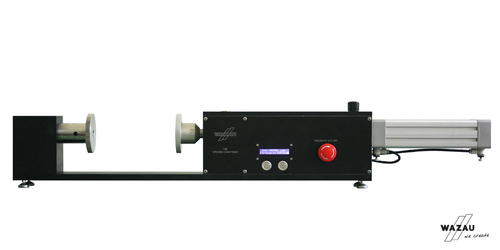
Torsion testing device TOR EN 531
The Wazau TOR device serves for simulating abrasive usage and ageing of cloths which is required as conditioning for several burning tests. To do that, a piece of the testing specimen is rolled up on a hose-like cylinder, clamped between two discs and then repetitively winded and compressed. An automatic timing and counting unit serves for monitoring and controlling the stress progress. Automatic pauses for changing the specimen orientation are available as well as an automatic stop after a specified number of revolutions.
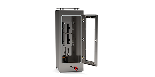
Testing device DO 160 V
Determination of the fire characteristics of aircraft equipment The defined flame treatment developed in the test procedure determines the resistance of the samples to the effects of flame. In the test chamber, a vertically arranged sample with the surface facing the gas burner is exposed to a defined flame. The test determines the length of the burned surface and whether and how long the sample burns. It is also recorded whether burning material detaches from the sample and falls off and how long the fallen part burns.
View Product
UL 2596
Torch and Grit Test with UL 2596 UL 2596 - TaG was developed for testing the resistance of battery housing materials to mechanical and thermal stresses. It is a safety test for battery packs that simulates how the battery pack reacts to fire conditions. The use of the Torch and Grit test aims to ensure that battery packs are not only electrically safe, but also robust enough to cope with potential fire conditions without compromising their insulation.. Material classification Based on the test results, materials are classified and graded to determine their suitability for different applications. This classification helps manufacturers and developers to select the right materials for specific applications to ensure the safety and reliability of the end products. Evaluation of battery housings for electric vehicles (EV) The UL 2596 standard defines the evaluation of battery housing materials for electric vehicles (EV) in terms of their thermal and mechanical performance. It enables the testing of the behavior of battery housing materials under extreme conditions such as high temperatures, pressure and ejected particles.

Testing device SPT DIN EN 348
Determination of the behavior of materials for protective clothing when exposed to small splashes of molten metal. . A welding wire is melted with a burner. The resulting droplets are directed onto a sample. The number of molten metal droplets impinging on a point of the vertically arranged sample required to produce a temperature rise of 40 K in a temperature sensor located behind the sample is counted. The burner and the feed rate of the welding wire are set and controlled by the device software.

Testing device HBP DIN EN ISO 6942
Procedure A exposes a specimen in a free-standing frame to a defined heat radiation for a defined time period. The intensity of the heat radiation is controlled by the distance between specimen and heat radiation source. After the testing the specimen and its different layers are examined for visual changes. In procedure B the specimen is fixed onto a calorimeter and exposed to a defined heat radiation. The time needed for a temperature rise in the calorimeter of 12°C and 24°C respectively is measured. On the basis of this data the heat throughput rate is calculated from the difference between passed and incident heat flow density. The software includes the calculations and evaluation of the standard. The power supply is provided by a three-wire plug 3 ~ 400 VAC (50/60 Hz) (5x32 A 6h CEE). The cooling device is equipped with an industrial cooler with closed cooling circuit, temperature control and alarm function for cooling the shield. It has a cooling capacity of 1700 W. Special features Data recording via control computer Software guided calibration and test procedures. Calorimeter protection by pressure switch preventing operation without co Industrial cooler Technical specifications Type of specimen: Textiles Test standards: DIN EN ISO 6942 Sensors: Temperature (calorimeter), water pressure sensor Supplies: 3 ~ 400 VAC / 12.5 kVA Dimensions: 1610 x 800 x 1500 mm (W x D x H) Weight: approx. 100 kg Show product leaflet Our partner Thomas Reinheimer Director Tel: +49 (0)30 3443088 / 89 Fax: +49 (0)30 3441976 Mail: reinheimer@wazau.com

Testing device HBP DIN EN ISO 6942 Table-top
Procedure A exposes a specimen in a free-standing frame to a defined heat radiation for a defined time period. The intensity of the heat radiation is controlled by the distance between specimen and heat radiation source. After the testing the specimen and its different layers are examined for visual changes. In procedure B the specimen is fixed onto a calorimeter and exposed to a defined heat radiation. The time needed for a temperature rise in the calorimeter of 12°C and 24°C respectively is measured. On the basis of this data the heat throughput rate is calculated from the difference between passed and incident heat flow density. The software includes the calculations and evaluation of the standard. The power supply is provided by a three-wire plug 3 ~ 400 VAC (50/60 Hz) (5x32 A 6h CEE).
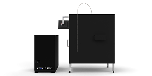
MMS - DIN EN ISO 9185 | ASTM F955
When testing materials according to DIN EN ISO 9185, defined quantities of molten metal are poured onto the specimen, which is held at an angle to the horizontal on a mounting frame. The damage is evaluated by placing a PVC film immediately behind and in contact with the specimen and assessing the changes in the PVC film after casting. When testing materials according to ASTM F955, defined quantities of molten metal are poured onto the specimen, which is held at an angle to the horizontal on a sensor board. Damage is assessed by having 2 calorimeters measure the temperature rise immediately behind the specimen.
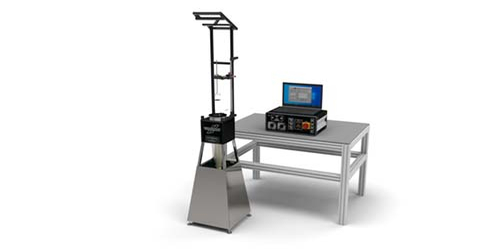
Testing device INB DIN EN ISO 1182
The device tests construction materials and assesses their burning behavior. The specimen are lowered into an oven with a temperature of 750°C. The oven is basically composed of the rack, an air stabilizer, the heater winding, thermocouples and the specimen holder. The oven temperature and the data collection is software-controlled. The software controls the heating phase of the oven and includes calculations and evaluations of the standard. The power supply for the heater winding is given by a switching power supply unit and a pulse-width modulation. The power supply for the controller is provided by an IEC-320 AC power cordset 230 VAC (50/60 Hz).
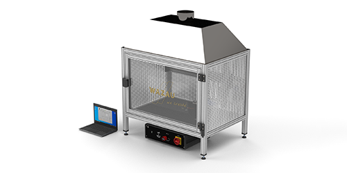
RPD - DIN EN 13274-4 (2/3)
A specimen is placed in a specimen holder or attached to a test head. In method 2, the specimen is passed over the burner for a defined period of time and then withdrawn again. In method 3, the specimen is drawn over the propane gas burner, which has a temperature of approx. 800 °C, at a speed of 60±5 mm/s. This is done in various burner positions. The burner can be moved in depth for this purpose. The specimen is moved by a spindle drive on a linear guide.
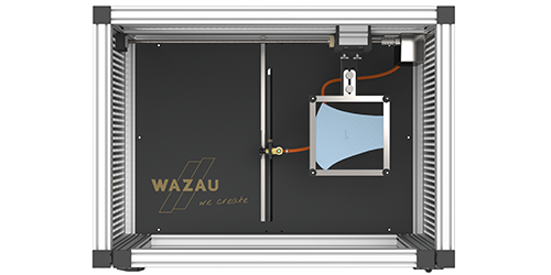
RPT - DIN EN 13274-4 (3)
The device is used to determine the flame effect on respiratory protective equipment, such as respirators. It is tested whether the specimen begins to burn or whether other hazards to the user may occur. A specimen is placed in a specimen holder. Testing with a test head is not possible with this instrument. If you require testing with a test head, use the RPD - DIN EN 13274-4 for this purpose. In procedure 2, the specimen is moved over the burner for a defined period of time and then withdrawn. In procedure 3, the specimen is drawn over the propane gas burner, which has a temperature of approx. 800 °C, at a speed of 60±5 mm/s. This is done in various burner positions. The burner can be moved manually in depth for this purpose. The specimen is moved by an electric spindle drive on a linear guide.
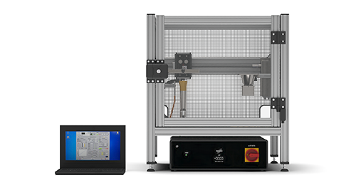
TPP - DIN EN ISO 9151
The device is used to determine the heat transmission of flame exposure to protective clothing against heat and flames. A classification of materials can be made by comparing the determined heat transfer indices, which serve as a reference for the relative heat transfer under the specified test conditions. A specimen is placed in a specimen holder. A calorimeter is placed directly on the inside of the specimen. The soecimen is then exposed to a heat flow of 80±2 kW/sqm generated by a propane gas burner. The time required to raise the temperature at the specimen by 24 °C is measured.
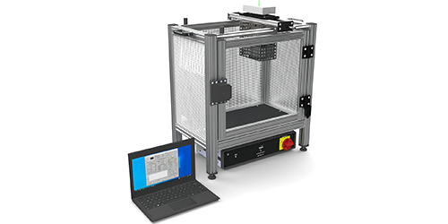
Contact heat testing device CHD DIN EN ISO 12127-1
The device determines the time threshold of a temperature rise of 10 °C in the calorimeter. In the test a heating cylinder is heated to a defined temperature and the specimen is put on the calorimeter. During the measuring the calorimeter is moved towards the heating cylinder with a defined speed of 5 mm/s and after contact a load of 49 N is applied. The temperature of the heating cylinder is adjustable from room temperature up to 500 °C. The power supply is provided by an IEC-320 AC power cordset 230 VAC (50Hz).
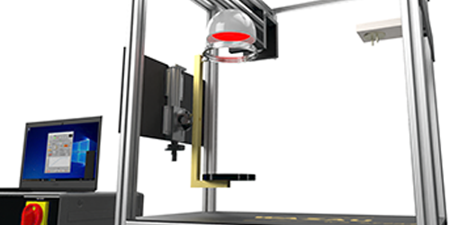
Testing device ECE R 118 Appendix 7
In the test device, a test specimen is exposed in a horizontal position to a heat flow through an electric heater. A tray is placed under the specimen to collect droplets. Absorbent cotton is placed in this tray to determine if the droplets burn. The heat flux from the electric heater is measured at a distance of 30 mm above a heat flux sensor. This heat flux is set and controlled by a PID controller, and the PID controller can be set to a manual or automatic mode, providing a fixed voltage signal at the manipulated variable (heater) and no feedback from the manipulated variable (heat flux sensor) to the PID controller. The software senses the heat flux and regulates or controls the manipulated variable of the electric heater.
Test device SPT - DIN EN ISO 12127-2

Glow wire testing device GPD DIN EN IEC 60695-2-10
The device is used to test the fire resistance properties of electrotechnical products and materials under IEC 60695-2-11, IEC 60695-2-12 and IEC 60695-2-13.The glow wire represents the fire source. The temperature is set in the software and controlled via a temperature controller, whereby the temperature controller is switched to manual mode during a test in order to achieve a fixed voltage signal at the control variable (glow wire) and thus avoid feedback of the control variable (temperature) to the temperature controller. The temperature at the glow wire is measured via an infrared sensor and can be set from 400 - 1000 °C. During the test, the sample is moved back and forth at a constant speed of approx. 11 mm/s to the glow wire. The dwell time between the sample and the glow wire can be variably set via a timer in the software. The effective value of the current flowing through the glow wire is displayed in the software. The sample table is pulled against the glow wire with a force of 1 N during the test. Specimens from 50 x 120 mm to 120 x 120 mm can be clamped in the specimen holder. The specimen thickness can be a maximum of 20 mm. The device is controlled by the device software, which is installed on a notebook or Mini PC. It controls the temperature of the glow wire and the linear drive of the sample holder carriage. The temperature of the pyrometer is displayed here, as is the setting of the penetration depth. Tests are started with the software and carried out automatically.
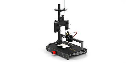
Needle flame testing device NPG DIN EN 60695-11-5
The device is used to evaluate the fire hazard by imitating the effect of small flames which can occur during faulty operation of devices and machines with a needle flame. The testing flame is the fire source to which a specimen is exposed for a defined period of time. The flame is confirmed by the testing arrangement and the calibration device. The temperature on the copper block is measured by a type K mineral-insulated metal-sheathed thermocouple (Class 1) under IEC 60584-2. The calibration device can automatically measure the time interval from 100°C to 700°C and determine the average value of three measurements. The calibration device does also have a digital and analog temperature output which can be used to determine the time intervals externally. The power supply is provided by an IEC-320 AC power cordset 100-230 VAC (50/60 Hz).
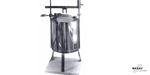
Testing device PNG DIN 4002-1-A1
The device tests construction materials and assesses their burning behavior. The specimen are lowered into an oven with a temperature of 750°C. The oven is basically composed of the rack, the heater winding, thermocouples, ignition flame and the specimen holder. The oven temperature and the data collection is software-controlled. The software controls the heating phase of the oven and provides calculations and evaluations of the standard. The power supply for the heater winding is given by a switching power supply unit and a pulse-width modulation. The power supply for the controller is provided by an IEC-320 AC power cordset 230 VAC (50/60 Hz). Technical specification
View Product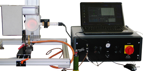
Testing device BVG DIN EN 13772
Burning behavior of curtains - measuring the flame spreading behavior of vertically fixed specimen exposed to large ignition sources. The device tests textiles and textile products, assessing the burning behavior and flame spreading behavior of vertically fixed specimen. The device consists of the burning box, a pneumatically controlled burner which is adjustable vertically and has more than 3 angle positions, the burner's moving mechanism, an irradiator, a calorimeter and the mechanism for fixing the specimen. The temperature control of the irradiator, the moving of the burner and the shield and the data collection is software controlled. The testing process can be defined in a simplified manner as follows: A heat flow with defined thermal rating is directed through a fixed plate in the lower part of the backside of the vertically fixed specimen. After 30 s a small flame (see DIN EN ISO 6941) is directed to a small piece of cotton tissue for 10 s where the tissue is fastened around the specimen's edge. The possible flame spread is measured through the breaking of the marking threads.
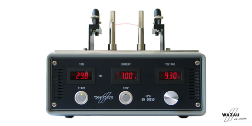
Testing device HPG DIN EN 60950 A4
Ignition attempt with a hot wire The device examines the ignition of specimen. In the testing procedure a wire is wound around the specimen five times and heated until it glows. The procedure contuinues until the specimen ignites or until 120 s have passed.
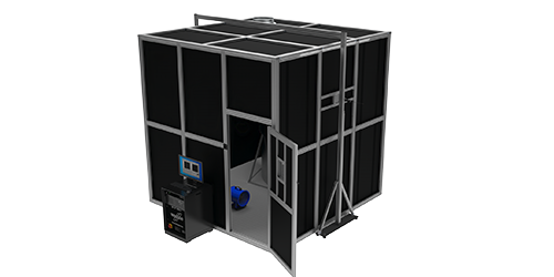
Testing device DIN EN 61034-1 27-m³-chamber
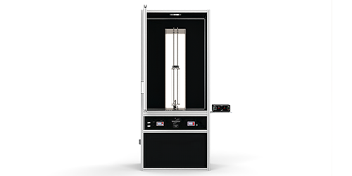
Testing device DIN EN 60332-1-1/DIN EN 60332-1-3
Flammability of cables The test device is suitable for carrying out vertical flame propagation tests with a 1 kW flame, on a wire, an insulated wire or a cable. The testing device is also designed for the evaluation of burning drops or parts

Smoke Box - DIN EN ISO 5659-2
Testing the fire behavior of building materials - Determination of the density of smoke emission The device is used to measure smoke generation on exposed surfaces of specimens made of materials or composites. Specimens are exposed to thermal radiation of up to 50 kW/m2 generated by an electric cone heater. The smoke emitted from the specimen is held in the chamber, and its density is determined using a photometric system. Alternatively, a pilot flame burner is additionally used. With the aid of an optional weighing device, the mass-based optical density can be determined. This test is an informative part of DIN EN ISO 5659-2. In addition, with the aid of an FTIR spectroscope (not part of the device), the toxicity of the smoke gases can be determined in accordance with IMO FTP CODE Annex 1, Appendix 2. The result of the smoke obscuration measurement is output as specific optical density. Additional modules

UL 2596
Test method for the thermal and mechanical stress resistance of battery enclosures The UL 2596 standard subjects material samples to thermal and abrasive stress. The results are then used to compare different materials in terms of their suitability for real-world applications. To do this, the sample is exposed to a gas burner flame. After 15 seconds of exposure to the burner flame, the sample is subjected to an abrasive blasting agent in combination with the burner flame for 5 seconds. This process is repeated 9 times, or until the sample breaks.

ISO 5657
Determination of the fire behavior of building materials - Flammability of building products when exposed to a radiant heater. The device is used to determine the flammability of building products (materials, composites and components). The specimens are exposed to heat radiation of 10 to 70 kW/m³ generated by an electric cone radiator. During this process, the specimen is pressed against a pressure plate with a defined force. In addition, the gases detaching from the specimen are ignited by means of a periodically applied pilot flame. The time that elapses until the specimen ignites is measured..

Cone Calorimeter ISO 5660-1
Reaction-to-fire tests - Heat release, smoke production and mass loss rate The test device is used to access the reaction of building materials to the effect of heat. Heat release, smoke production and mass loss rate are measured. The main function of the Cone Calorimeter is based on the knowledge that the net heat of combustion is in fact proportional to the amount of oxygen required for combustion. The ratio is approximately that 13.1 x 1000 kJ of heat is released per kilogram of oxygen consumed during combustion. The samples are irradiated under laboratory conditions, ignited by sparks and thereby burned. They are exposed to thermal radiation at fixed intervals between 10 kW/sqm - 75 kW/sqm and the changes in oxygen and gas concentration are measured. The principle is called the "oxygen consumption principle" and originates from calorimetry. Furthermore, the flow rate in the exhaust pipe and the loss of mass of the sample are measured. Smoke obscuration is measured as the intensity of the laser light that is transmitted through the smoke in the exhaust pipe. The measurement is used to calculate the extinction coefficient according to Bourger's law. The test results are used to determine smoke production and smoke production rate.
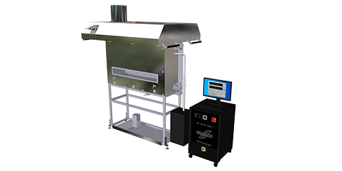
Testing device DIN EN ISO 9239-1
Description of fire behavior in case of exposure to a radiant heater. The results of this test process are the basis for evaluating one aspect of the fire behavior of floor coverings. The heat radiation sent to the sample by the heater simulates the likely degree of stress to the floor in a corridor of which the top side is affected by flames and/or heat gases during the early phase of the development of a fire in a room or section against the air flow. The sample is placed in a horizontal position under the gas-heated radiant heater that is inclined by 30° against the horizontal line. The sample is exposed to a certain heat stream. A pilot flame is brought into contact with the hot end of the sample. After the ignition, every forming flame front is determined and the horizontal spread of the flame front along the sample length is recorded as the time needed by the flame front so that it spreads over the determined distance. The smoke development in the flue is recorded by registering the weakening of light during the test. The software serves for the control and measurement data recording. It provides the functions of calibrations, valve control, preheating and CHF calculation.
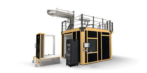
SBI - EN 13823
Reaction test to a thermal attack of a single burning item, on construction products other than floor coverings. The test is used to classify building materials according to DIN EN 13501-1 for the European classes A2, B, C and D. Two specimen wings are mounted vertically at a 90 ° angle to each other on the specimen trolley. In the lower corner formed by the specimen wings, a sand bed burner simulates a burning item, e.g. a burning waste container. A second identical burner, which is ignited shortly before the main burner, serves to determine the heat development and heat release of the burner on its own. In addition to the development of the fire, it is determined whether parts of the specimen drip off or fall off.
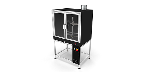
Testing device DIN EN 71-2
The testing device determines the flammability of toys. The device is used to test the fire resistance properties of toys and materials under DIN EN 71-2. Specimen of different kinds are fixed to different specimen holders and exposed to a burner flame. A record which lists all the characteristics of the fire test has to be written after all standard tests.

Testing device Spread of Flame ISO 5658-2
Lateral spread of flame on vertically arranged construction products The results of this testing procedure are used as a basis for evaluating the burning behavior of a lateral flame which spreads along a specimen. The heat radiation which a radiant heater applies to a specimen simulates the probable degree of stress that acts upon a specimen in a fire scenario. The sample is placed in a horizontal position under the gas-heated radiant heater that is inclined by 15 +/- 3° against the horizontal line. The sample is exposed to a certain heat stream. A pilot flame is brought into contact with the hot end of the sample. After ignition any flame front that forms is registered and its horizontal spread along the length of the specimen is recorded as the time the flame front needs for spreading over defined distances. Controlling the device and measurement data recording as well as data processing is done via the software. It provides the calibration, valve control, preheating and CHF calculation.
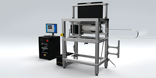
Testing device Spread of Flame ISO 5658-2 / IMO A 653(16)
Lateral spread of flame on vertically arranged construction products The results of this testing procedure are used as a basis for evaluating the burning behavior of a lateral flame which spreads along a specimen. The heat radiation which a radiant heater applies to a specimen simulates the probable degree of stress that acts upon a specimen in a fire scenario. The sample is placed in a horizontal position under the gas-heated radiant heater that is inclined by 15 +/- 3° against the horizontal line. The sample is exposed to a certain heat stream. A pilot flame is brought into contact with the hot end of the sample. After ignition any flame front that forms is registered and its horizontal spread along the length of the specimen is recorded as the time the flame front needs for spreading over defined distances. For the IMO standard an exhaust flue with thermocouples is used to calculate the maximum heat release rate and the released total amount of heat. Controlling and measurement data recording is done with the software. It provides the calibration, valve control, preheating and CHF calculation.
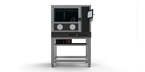
UL 94 | EN 60695-11-10 | EN 60695-11-20 - Model 2020
Tests determining the fire hazard. The test device is equipped with a 4-axis burner position control. Two of the axes are moved electrically (burner height, burner angle) and controlled by the integrated mini PC. The operation is done via a touch screen display. The gas control is also electronic, controlled by the device software. The device software supports you during the tests by specifying the exposure times, setting time events, moving the burner vertically into the test position and tilting it if necessary. If it is necessary to track the flame during a test, the software remembers the procedure of the first test and can then follow this procedure during subsequent tests. Furthermore, a largely automatic calibration device is provided for adjusting the flame output. Depending on the standard, tests can be performed with the 50 W test flame or the 500 W test flame. For safety reasons, the burner is equipped with an electronic pilot flame safety device, which is implemented with a thermocouple.

UL 1581
Determination of the flame propagation through electrical cables and wires The test equipment is used for testing with horizontal and vertical test specimen arrangement. Vertically oriented test specimen The cable under test is exposed to a 500 W flame (125 mm high) three times for 60 seconds with an interval of 30 seconds. This determines whether the flame is propagated longitudinally. Horizontally oriented test specimen The cable under test is exposed to a 225 W flame (50 mm high) for 30 seconds. This determines whether the flame is propagated longitudinally. The tests provide information on whether the specimens leak or release emissions into the environment during flame impingement.
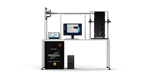
Prüfeinrichtung DIN 4102-1 Anhang B
The test device DIN 4102-1 Annex B is used to determine the reaction to fire of building materials. Material samples are exposed to a defined flame. The resulting smoke density is measured with an electronic light measurement system.

DIN 4102-1 Annex A
The DIN 4102-1 Annex A testing apparatus is used to determine the smoke emission of building materials during decomposition under smoldering conditions. Material samples are placed in a glass cuvette inside a quartz tube. A ring furnace is slowly moved over the quartz tube. The resulting decomposition products are blown into a measuring tube using compressed air. The resulting smoke density is measured using an electronic light attenuation measurement system.
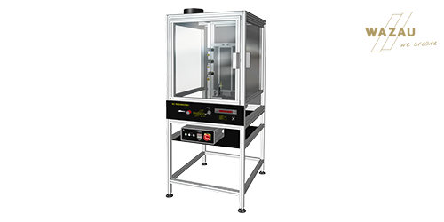
ISO 15025/6940/6941
The test device allows testing the properties of textile materials in response to brief contact with a small flame. In its basic configuration the device is designed for tests according to DIN EN ISO 6941. For tests according to DIN EN ISO 15025 and DIN EN ISO 6940 the device can be configured accordingly. A set of specimens of is exposed to a flame for a defined time. ISO 6941: The spread of the flames in vertical direction is tested. The time elapsing from the beginning of the test until the marking threads are torn is measured. ISO 6940: The duration of the flame exposure is determined from which the specimen ignites or does not ignite. ISO 15025: The spread of the flames in vertical direction as well as the afterburning and afterglow time are determined.

ISO 15025/6940/6941 Tabletop
The test device allows testing the properties of textile materials in response to brief contact with a small flame. In its basic configuration the device is designed for tests according to DIN EN ISO 6941. For tests according to DIN EN ISO 15025 and DIN EN ISO 6940 the device can be configured accordingly. A set of specimens of is exposed to a flame for a defined time. ISO 6941: The spread of the flames in vertical direction is tested. The time elapsing from the beginning of the test until the marking threads are torn is measured. ISO 6940: The duration of the flame exposure is determined from which the specimen ignites or does not ignite. ISO 15025: The spread of the flames in vertical direction as well as the afterburning and afterglow time are determined.

ISO 6941/ECE-R 118 Annex 8 tabletop
The test device allows testing the properties of textile materials in response to brief contact with a small flame. A set of specimens of is exposed to a flame for a defined time. The spread of the flames in vertical direction is tested. The time elapsing from the beginning of the test until the marking threads are torn is measured. ECE-R 118-8: The spread of the flames in vertical direction as well as the afterburning and afterglow time are determined.
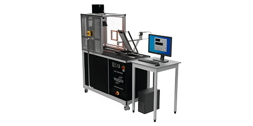
Radiant Panel/ Surface Flammability - ASTM E 162/ASTM D 3675
Test for surface flammability of materials The test equipment WAZAU ASTM E162 / D3675 is used to measure the surface flammability of materials and products. The specimen inclined at 30° to the vertical is heated by a radiant heater arranged vertically. The specimen is ignited with a burner at the upper edge, which is closer to the radiator surface. The time is measured that elapses until one of the marks, which are placed 76 mm apart, is reached.
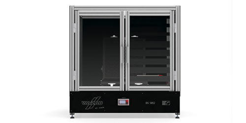
Test equipment BS 5852
The test device enables tests on the flammability of upholstered furniture. A build-up of the upholstery as in the application is placed on a 2-part, rectangular holding frame. Various defined flames from a burner act on the groove between the frame parts for a set period of time. The extent of an open fire and that of a smoldering fire are determined.

Test equipment ISO 6925
The test device enables tests to be made on the flammability of textile floor coverings. A specimen is covered with a template with a circular cutout and a methamine tablet is placed in the center of the specimen and ignited. The time that elapses until the fire reaches the edge of the stencil or goes out is determined
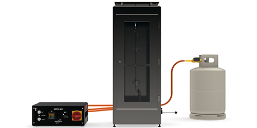
Prüfeinrichtung ASTM D6413
The test equipment enables the testing of the fire resistance of textiles (vertical test). A textile specimen is clamped in a vertical frame and exposed to the flame of a gas burner for a defined time. The burning time, the afterglow time, and the extent of charring and length of fire spread are determined. In addition, the tensile strength of the burnt specimen is determined by hanging weights on the specimen.
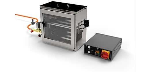
BKF - DIN 75200 | MVS 302 | ISO 3795
The test device enables tests on the burning rate of materials or composite materials used in the passenger compartment of motor vehicles. A precisely defined pilot flame acts over a certain period of time. A specimen is clamped horizontally in a holding frame. The flame from a burner, precisely defined in size and orientation, acts on an edge of the specimen over a defined period of time. The test standards specify the exact parameters of the test procedure (flame orientation, exposure). Optional modules Timer unit with timer, solenoid valve and flame protection Mechanical piezo igniter for burner Stop watch Additional specimen holders for specific standards (VW, Toyota, Nissan etc.)
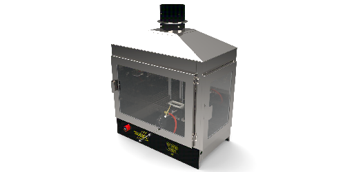
Testing device BBK – EN ISO 11925-2 | DIN 4102-1 B2
Tests determining the risk of fire in construction products. In this procedure, the flammability of construction products is tested with a small flame acting directly on the product. A match flame is simulated. The specimens are arranged vertically. The flame is held either at the surface or at the edge of the specimen. The spread of the flame on the surface of the specimen is determined.

Test equipment IEC 60331-11
The test equipment enables circuit integrity tests for electrical cables and insulated wires in the event of fire. Electrical cables and insulated wires are exposed to a flame with a temperature of at least 750 °C. During this, current is applied to the cables and wires. It is determined how long it takes for a conductor to be interrupted.
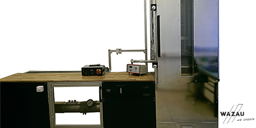
Testing device fire shaft DIN 4102-15
Assessment of the fire behaviour of building materials The test method is used to assess the fire behavior of building materials. The flame treatment in the test procedure simulates the resistance of products to the effects of flame. The test method is also suitable for checking the uniformity of behaviour in the presence of flames and for comparing products. In this test method, four building material samples are arranged in a fire shaft like a chimney around a square gas burner and exposed to a defined flame treatment.
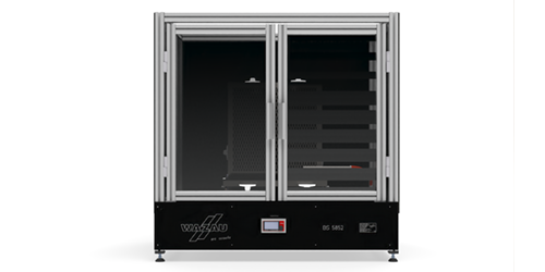
Test equipment EN 1021 Part 1 & 2
The test device enables tests on the flammability of upholstered furniture. A build-up of the upholstery as in the application is placed on a 2-part, rectangular holding frame. Various defined flames from a burner act on the groove between the frame parts for a set period of time. The extent of an open fire and that of a smoldering fire are determined.
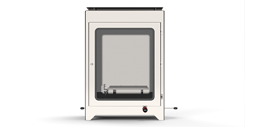
Testing device DO 160 H /-60 G
The defined flame treatment developed in the test procedure determines the resistance of the samples to the effects of flame. In the test chamber, a vertically arranged sample with the surface facing the gas burner is exposed to a defined flame. The test determines the length of the burned surface and whether and how long the sample burns. In horizontal tests the rate of combustion is determined. In 60° tests, the length of the burned surface is determined and whether and how long the sample burns. It is also recorded whether burning material detaches from the sample and falls off and how long the fallen part burns.
Testing device SPT DIN EN 348
Determination of the behavior of materials for protective clothing when exposed to small splashes of molten metal. . A welding wire is melted with a burner. The resulting droplets are directed onto a sample. The number of molten metal droplets impinging on a point of the vertically arranged sample required to produce a temperature rise of 40 K in a temperature sensor located behind the sample is counted. The burner and the feed rate of the welding wire are set and controlled by the device software.
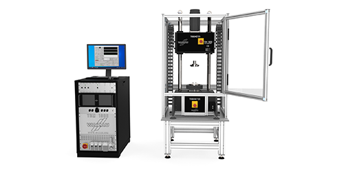
Tribometer TRM 1000
Tribological testing in rotational movements The tribometer is used for examining and simulating friction and abrasion processes under sliding load. It can be operated without lubrication with solid objects and with fluid lubricants with boundary or mixed friction. Thus both materials and lubricants can be examined. During the standard testing procedure a stationary specimen (pin or ball) is pressed against the front surface of a rotating disc with a defined normal force. Both specimen are arranged vertically, the rotating disc being positioned above. Other testing procedures can be conceived as well. The normal force is provided by the movement of the motor block via a motor spindle system. A spring situated in the sensor block under the linear table is used as absorption of the normal force. The drive unit is a servomotor which can be regulated continuously variably between 0.1 and 3000 / 4000 / 6000 min-1. The actual testing device consists of the motor unit, the drive unit and the load component. The assemblies are fixed n top of each other in a slideable manner to two vertically positioned bars. During the testing a continuous measuring of the normal force, the ambient temperature in the bowl, the linear distance of both friction materials, the rotational speed and the friction torque takes place. The specimen bowl can be heated between RT and 150°C. A K-type thermocouple in the specimen bowl provides temperature measuring and adjusting. The displacement is measured between lower and upper specimen position. The displacement is measured without contact by an optical laser displacement sensor. The active torque is registered by a torque shaft and the reactive torque is measured by a torque module. All measurement signals are sent to the control cabinet and processed accordingly. The data collection is provided by a multi-functional data collection module with a resolution of 16 Bit and the software provides a measuring frequency of 0.01 - 100 Hz. The rotational speed is registered digitally with a measuring frequency of 4 Hz. The software is used for controlling and measurement data recording purposes. Additional modules Power input module Temperature input module Inertia mass simulation module Oil recirculating lubrication module Low temperature module High temperature module Heating ring module Four ball mechanism module Linear oscillation module
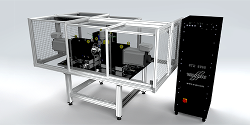
Tribometer UTM 2000
Tribological testing in rotational movements The tribometer is used for examining and simulating friction and abrasion processes under rolling and sliding load. It can be operated without lubrication with solid objects and with fluid lubricants with boundary or mixed friction. Thus both materials and lubricants can be examined. In the standard testing procedure two discs are pressed onto each other under a defined normal force. Both specimen are arranged vertically and both test-discs rotate. The normal force is applied by a motor spindle system. The drive unit is a servomotor which can be regulated continuously variably between 0.1 and 3000min-1. The actual testing device consists of the motor unit, the drive unit and the load component. During the testing a continuous measuring of the normal force, the linear distance of both friction materials, the rotational speeds and the friction torque takes place. The temperature is measured and controlled by a type K thermocouple in the oil reservoir. The lubricant is transported by an oil recirculating lubrication system. The displacement is measured between the two drive units. The displacement is measured without contact by an optical laser displacement sensor. The active torque is registered by a torque shaft. All measurement signals are sent to the control cabinet and processed accordingly. The data collection is provided by a multifunctional data collection module with a resolution of 16 Bit and the software provides a measuring frequency of 0.01 - 100 Hz. The rotational speed is registered digitally with a measuring frequency of 4 Hz. The software is used for controlling and measurement data recording purposes.